
Regenerative Turbine Pumps: The Clear Solution for Volatile Fluids
 From Fluid Handling
Today, two main types of pump dominate the scene in the chemical process industries: positive displacement pumps and impeller pumps. For pumping applications that involve highly volatile fluids, the choices are limited.
When such fluids are allowed to flash to vapor during pumping, the eventual collapse of the entrained vapor bubbles will create cavitation that can severely damage pump internals. Unlike many other pump types, the regenerative turbine pump — a type of impeller pump — is becoming the preferred type of pump for situations in which transient cavitation conditions occur, such as during the handling of high-volatility fluids. The various attributes of regenerative turbine pumps are discussed below.
Pump Primer
In all positive-displacement pumps (either reciprocating or rotary), the action of the pump alternately fills and then empties one or more cavities with the pumped fluid. Fluid is pushed into a created volume, by both the pressure on the free surface of the inlet fluid and the static head above the inlet. With the appropriate valving, the destruction of this created volume then pushes the fluid out against whatever pressure exists at the outlet.
By comparison, the impeller pump imparts kinetic energy to the fluid, which is borne as potential energy or pressure. In general, positive-displacement pumps attempt to maintain a given flow rate regardless of required pressure, while impeller pumps attempt to maintain pressure regardless of flow.
Within each pump category, many subtypes have been developed to improve pump performance for different types of fluids. For instance, the most popular impeller pump is the centrifugal pump, with its curved vanes, while the regenerative turbine pump, shown in Figure 1, is another lesser-known variation.
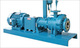
Fig. 1 - The fluted impeller is the hallmark of a regenerative impeller pump. Through centrifugal forces, this impeller propels the fluid radially outward. The enclosing channels direct the fluid into twin vortices around the impeller blades, also shown in Figure 2. |

Figure 1. The fluted impeller is the hallmark of a regenerative impeller pump. Through centrifugal forces, this impeller propels the fluid radially outward. The enclosing channels direct the fluid into twin vortices around the impeller blades, also shown in Figure 2.
Overall, the impeller pump family includes several "turbine" pumps. These include the horizontal-shaft diffuser pump, and the vertical-shaft deep-well centrifugal pump. Turbine pumps can also be subcategorized as vortex, periphery or regenerative turbine pumps, based on the shape of the blades that impart energy to the liquid, and the direction of the liquid as it leaves the blade.
All centrifugal pumps take liquid in at the center of the impeller. Some push it radially outward, with no axial component to the velocity. The propeller moves the liquid along the axis of the drive shaft, and imparts no radial component to the velocity of the pumped fluid.
By comparison, mixed-flow pumps are often called turbine pumps, because their impellers — part axial and part centrifugal in design and function — move the liquid outward from the center. These impellers impart both a radial and an axial component to the fluid flow. In all these pump types, the liquid passes through the impeller only once, and thus has all the energy added in a single pass through the pump blades. By comparison, in a regenerative turbine pump, the liquid is exposed to the impeller many times, with additional energy being imparted to the fluid each time it passes through the blades, allowing substantially more motive force to be added. This allows for much higher pressures to be achieved in a more-compact pump design. In fact, of all the centrifugal pump types that this author is familiar with, the regenerative turbine pump is the only one in which the fluid passes the impeller blades more than once as it travels from inlet to outlet for a given impeller stage.
Figure 2. As fluid flows through the impeller-housing channel, vortices are formed on either side of the impeller vanes (shown above). Since the fluid not keep up with the impeller, it completes its loop in the helix and re-enters the impeller at blades that trail those blades. This pattern imparts additional energy. |
Fig. 3 - As fluid moves form the inlet to the outlet, pressure mounts continuously in the vicinity of each impeller blade of the regenerative turbine pump, with subsequent passes though the impeller channels adding energy to the vortex. This energy manifests itself as pressure. |


How regenerative turbine pumps work
A typical impeller and housing of a regenerative turbine pump are shown in Figure 1. The fluid is in contact with the fluted portion of the impeller. The impeller, through centrifugal forces, propels the fluid radially outward. The enclosing chambers conduct the fluid into twin vortices around the impeller blades, as shown in Figures 2 and 3.
A small pressure rise occurs in the vicinity of each impeller blade. Vor-spring, form it into a circle, and lay it on the impeller blade. As you follow the coiled spring, you would see the progression of movement from one blade to the trailing blade.
Depending on how far the spring has been stretched (the distance between coils could be large relative to the coil diameter) the pitch of one loop may span more than the distance between adjacent blades. As the discharge pressure increases, the pitch of the loops in the helix get smaller, in a manner comparable to compressing the spring. It has been visually confirmed that as the discharge pressure increases, the helical pitch of the fluid becomes shorter.
With this mental picture in mind, one of the most important features of the regenerative turbine pump is pointed out. First, the vapor bubbles found in the incoming fluid, because of the inertia of the liquid in the vortex, are forced away from the metal walls of the pump into the center of the helix (spring). Second, the rate of pressure increase from inlet to outlet is much lower than for any other type of pump, because the pressure is building continuously around the pumping channel, rather than in a single quick passage through the blades. The shock of collapsing bubbles is virtually non-existent, and any bubbles that do collapse impinge on adjacent fluid, not on the metal pump components.
Related Products
regenerative pumps product lines
Roth Pump offers a variety of of both chemical & industrial pumps for improving the operation and efficiency of commercial systems
-
Chemical Pumps
Overview of available regenerative turbine chemical pumps
-

Industrial Pumps
Overview of available industrial regenerative turbine pumps